I have a weather station problem. Well, a series of problems, really. I think I’ve had 3 of them over the past several years, but they all suffer from one or more problems.
They don’t tell me Dew Point
Relative humidity is inferior and I’ll fight anyone who says otherwise.They lose connectivity to their sensors
I don’t need hyper-local data. I just want to know the temperature in my neighborhood, not literally in my yard. There’s no reason to deal with this.They eat batteries
The outdoor temperature sensor in particular seems like it’s always crying for a new battery.They’re ugly
Who wants THIS on their wall??
If I build my own, I can fix this. My aesthetic is mid-century modern IoT. I think it’s funny to make an internet-connected weather station and then put it in a retro-looking container with analog gauges.
The Architecture
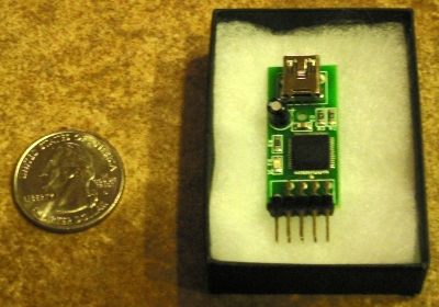
Processor
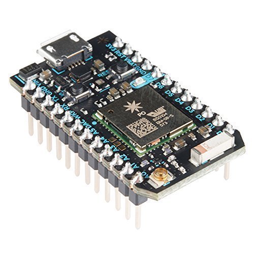
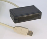
I have a Particle Photon that’s not assigned to anything at the moment. It’s cheap, wi-fi enabled, powered directly by USB, and you can flash new software to it over the web. It’s actually really powerful and at $19, it’s not even the most expensive thing in the build.
Gauges

For the all-important dew point, I’m using a Juken X27.168 Stepper Motor. It has internal stops at each end of a 315° rotation, so it’s easy to find its zero position at start-up.
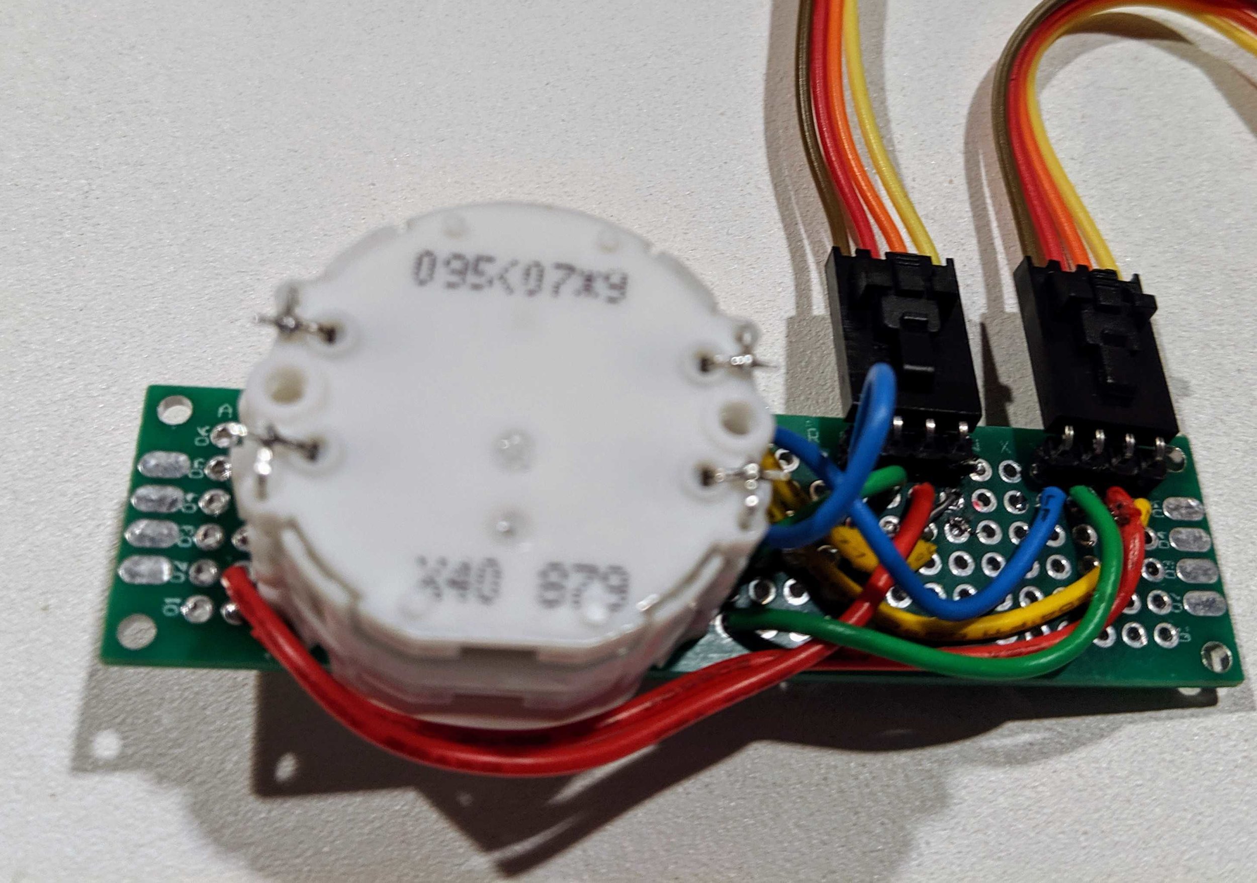
I want to display temperature and daily high temperature on one scale. To do that, I need a Juken X40 879B dual-spindle stepper motor.
They’re very low torque, but they can be driven at USB voltages, so it keeps the power situation simple.
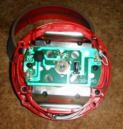
Cabinet

I need a nice looking container to put the whole thing in. I like the look of this clock. It’s more than 8 inches across, so there should be plenty of room for everything inside.
I’m replacing the face, but I’ll reuse a couple of the hands.
Building It
Software
The Photon has plenty of memory for an HTTP Client, a JSON parser, and a library to drive stepper motors. Everything can be globally scoped and reused as long as the thing is powered on.
The first free weather API I found is OpenWeatherMap. It doesn’t have dew point explicitly, but as everyone knows:
        Cγ(T,RH)
Tdp = ⎼⎼⎼⎼⎼⎼⎼⎼⎼⎼⎼⎼
       b - γ(T,RH)
where
         ln(RH/100) + bT
γ(T,RH) = ⎼⎼⎼⎼⎼⎼⎼⎼⎼⎼⎼⎼⎼⎼⎼⎼⎼
             C + T
and
b = 17.67, C = 243.5,
T = temp (°C),
RH = relative humidity
So computing dew point and stepper motor positions is just a little algebra. I passed Algebra last century, and I still remember a lot of it.
The firmware is at https://github.com/powerfulmojo/WeatherMojo.
Particle variables and functions are documented here.
Electronics
The X27.168 and the X40.879B are driven by L293D dual H-bridges. They’re about 80¢ each when you buy 10. They have built-in flyback diodes to protect the Photon from any inductive-load-related nastiness that comes back from the motors.
Here’s what the design looks like:
schematic
It’s a lot of wires, but it’s not very complicated. Each H-bridge has 4 power pins, 4 ground pins, 4 processor connections, and 4 motor connections. I was able to squeeze everything onto a 24x18 perfboard.
Since the X40 has front contacts, I soldered that to its own board and used right-angle headers to connect jumper wires to it.
I had to fiddle with pin assignments to get the motors spinning in the right direction, but that’s all software. I did it after everything was soldered in place.
The Gauges
The face is a stainless steel disc I got from an eBay seller. I drew up some concept gauge layouts to see what I liked.
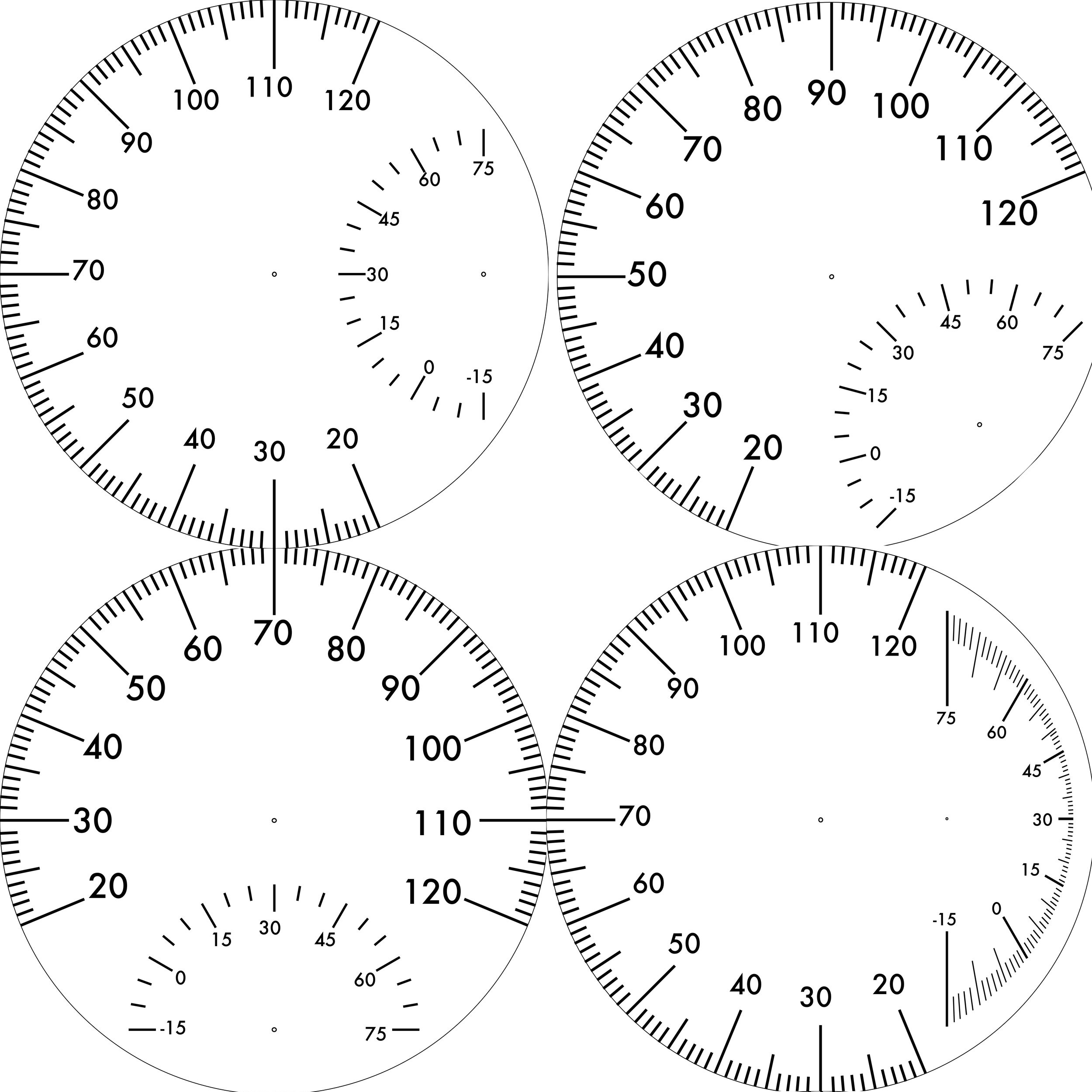
I printed the gauges on some water decal paper on my laser printer & applied it to the steel in one piece.
The hardest part of the project was actually attaching the gauge hands. The contacts on the temperature motors are on the front, so all of the connections have to be made between the motor body and the back side of the face. The spindles only stick out a few millimeters in the first place, so I spent a whole day driving back and forth to the hardware store trying out parts I might use to mount the hands to the motor.
If you try this, save the clock mechanism. It already has parts that fit the clock hands. That way you only have to adapt them to fit the motors.
The Finished Product
I love it! I probably ended up spending as much as I would on a decent weather station, but this one shows me data I actually care about.
Front
In Situ
Back
The big hand shows current temperature while the skinny one shows the highest temperature seen today. Most of the time they’re overlapping but as the temperature cools down, it shows you how hot it got today. It resets every morning at 9:00am so you still have a little time to see yesterday’s high at breakfast.